Shmøergh Hog
The making of a simple analog synth
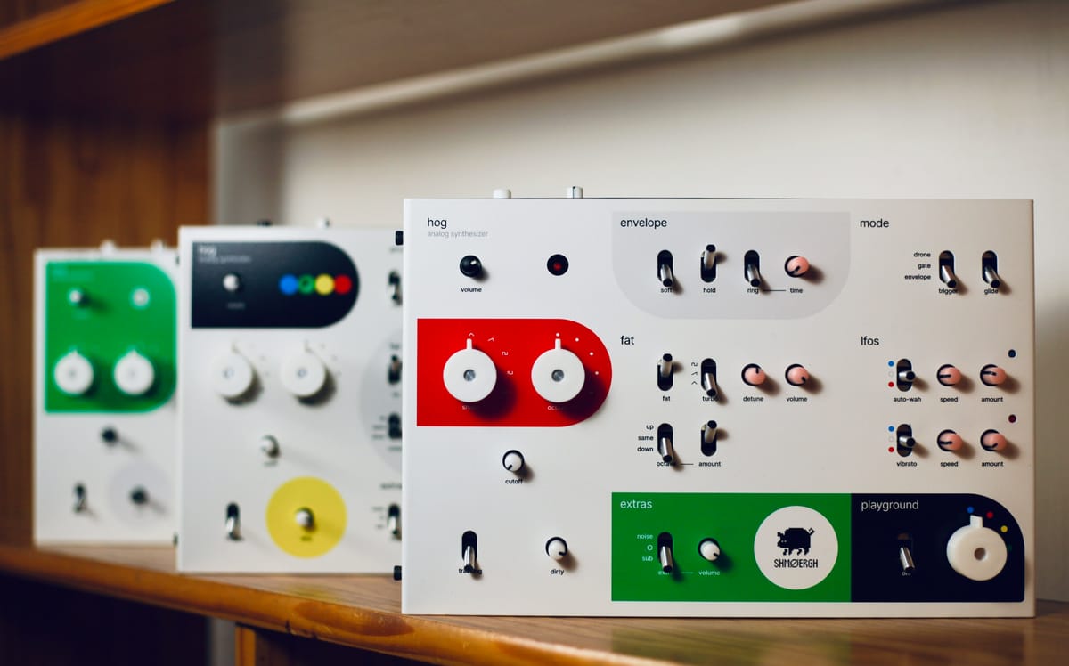
We finished the first version of a synthesizer that starts to resemble a real product. It's the same concept that I've already written about – a simple switches-over-knobs style analog synth for live performance, called Hog – but with completely reworked circuitry and enclosure.
This post is about our process and how the Hog came to be, so I'm not going to write about how the instrument works. But to give you a bit of context, here is an overview of the main features:
- Fully analog signal path and control circuits
- Two voices with triangle, sawtooth, square wave shapes
- Sub or noise extra voice
- Narrow and variable pulse width for voice 1
- 10 octave precision
- 5 octaves switch
- Voice 2 with +/- 1/2 octave and detune
- 2 selectable LFOs for auto-wah and vibrato
- Playground with variable modulation paths
- Custom quick envelope system
- Glide
- Variable gate modes (envelope, gate and drone)
- MIDI upgradable
- Customizable, hackable, open-source
If you want details of the synth itself you can head over to shmoergh.com.
The idea of the Hog came when we were messing around with the A1 prototype and found it tedious and time consuming to switch between sounds that are actually usable e.g. in a band. So we decided to design a very simple analog synth that has killer sound, and through purposeful limitations, it is very easy to work with. Kinda the opposite of what you expect of today's synthesizers with "endless possibilities".
A serious hobby
I experiment with electronics and build instruments in my spare time simply because I enjoy it and I love to learn. I do it only over the weekends so it took about two years to get to this point with the Hog.
I work on Shmøergh with my best friend, Flame. Usually I design concepts and visuals, design and build electronics and Flame works on industrial design, which includes 3D stuff and hardware manufacturing. Our not so unsophisticated "process" is that we share everything and talk to each other. We both have jobs in tech (Flame is director of design at LastPass, I'm head of design at Ghost) and neither of us built or launched any physical product yet, so we're both just learning and having fun.
Sound from a flower pot
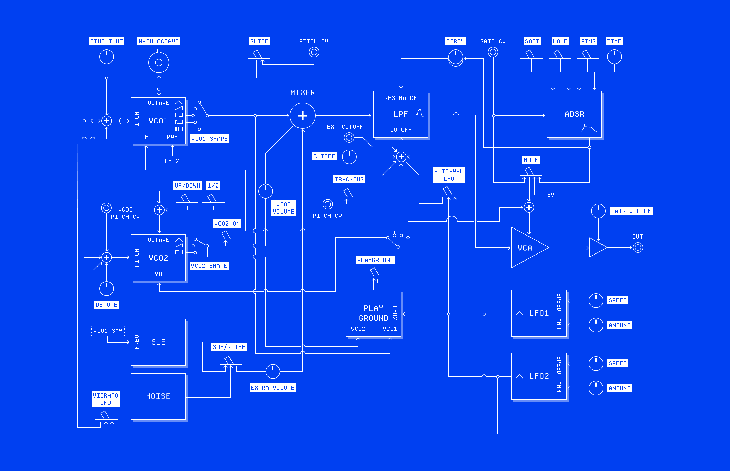
An analog synth is built out of self-contained modules. It consists of sound sources like oscillators, modifiers like filters and modulators, and utilities that shape the sound further. These modules are connected to each other to build up a complete system. The architecture of the Hog is fairly simple and follows classic subtractive synthesis principles: the sound sources have a lot of frequency content like a sawtooth or square wave. These pure waves then run through a filter, and finally the sound is shaped and modulated by various voltage controlled utilities.
Circuit design
When it comes to the actual circuits of subtractive analog synths, most builders (even big ones) are remixing and refining what already has been figured out in the 60s by Robert Moog. So the best first step is to find sources to steal get inspiration from. For me probably the two biggest source are the modules of Befaco and Moritz Klein's channel. However, I don't just blindly copy circuits but also take the time to thoroughly understand how they actually work. Apart from fulfilling my thirst of knowledge, understanding circuits also helps debugging and refining details later in the build process.
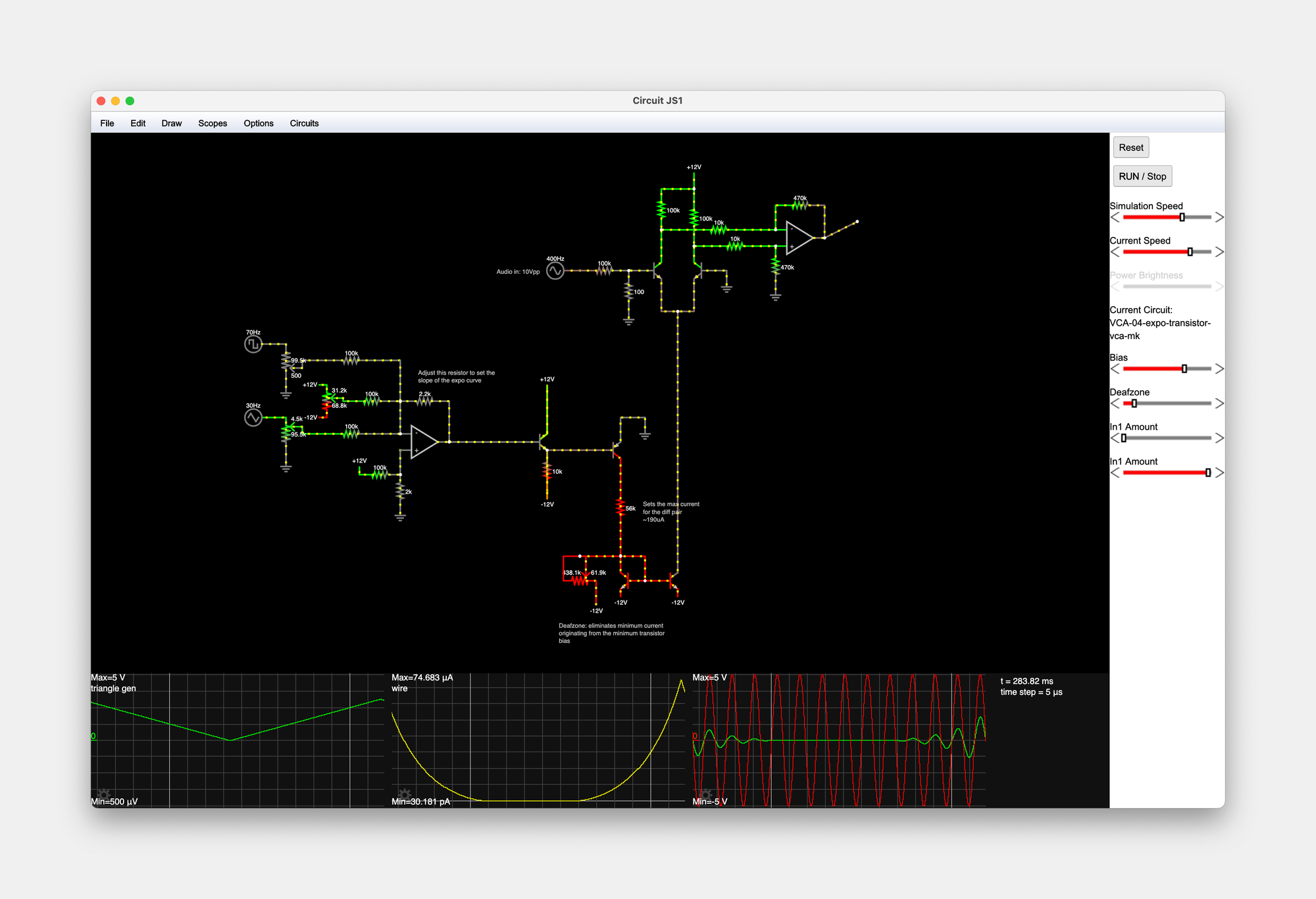
Once I know what's going on in a circuit but I want to fine tune or change something then I simulate it in CircuitJS – a fantastic browser based tool –, or in LTSpice when I need more accurate measurements or complex responses.
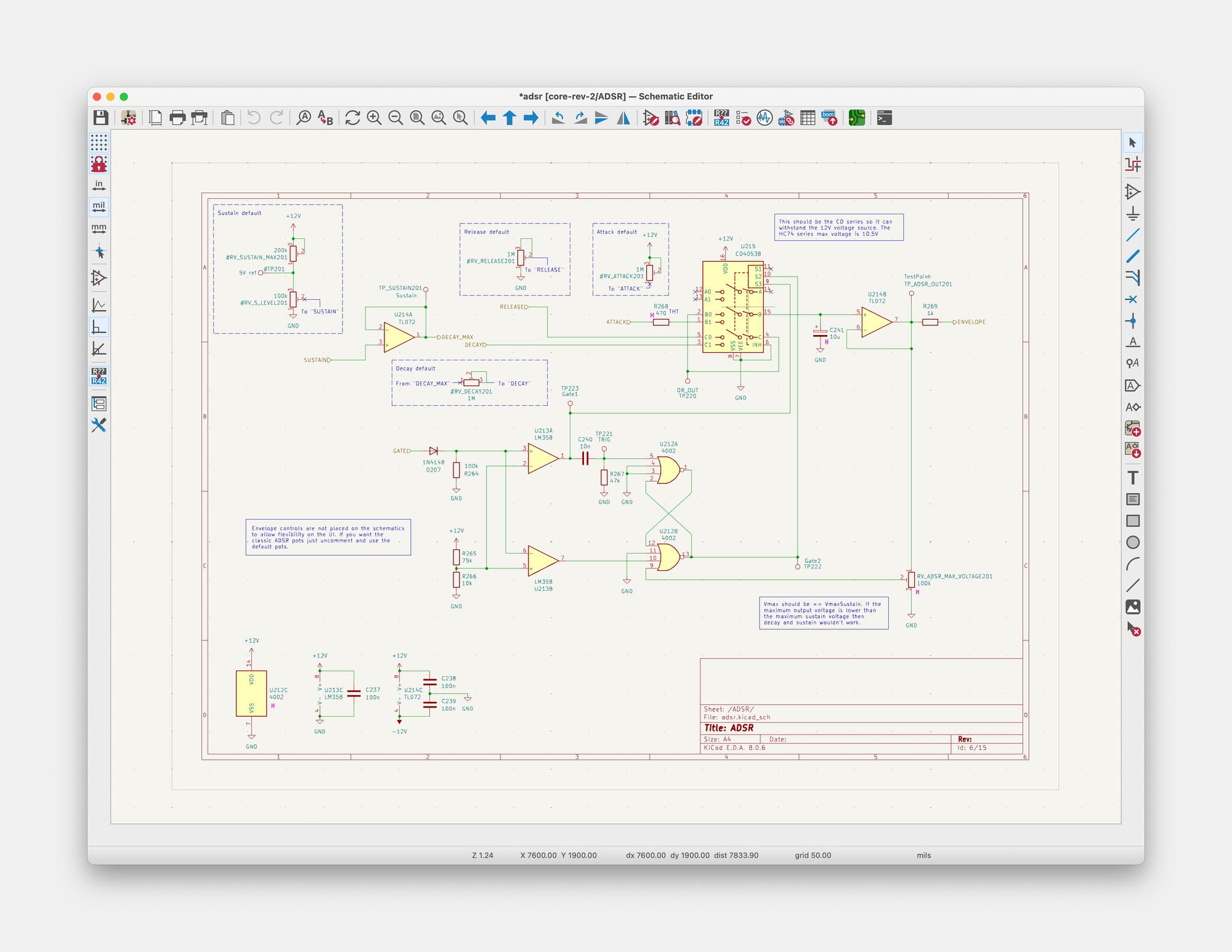
Next, I draw the schematics in KiCad (which is a free tool that comes with a price of unorthodox UX solutions and lots of frustration). When I'm done with the circuit design, I print it on paper which then I use as a blueprint to build the first prototype.
What comes next is probably the most exciting part of the process: building the circuit on a breadboard. This is the moment of truth when the connection of actual, physical things like resistors, capacitors and integrated circuits do or don't do what you simulated on a computer. This is when the directed flow of electrons becomes music which I find fascinating, magical and sometimes unbelievable.
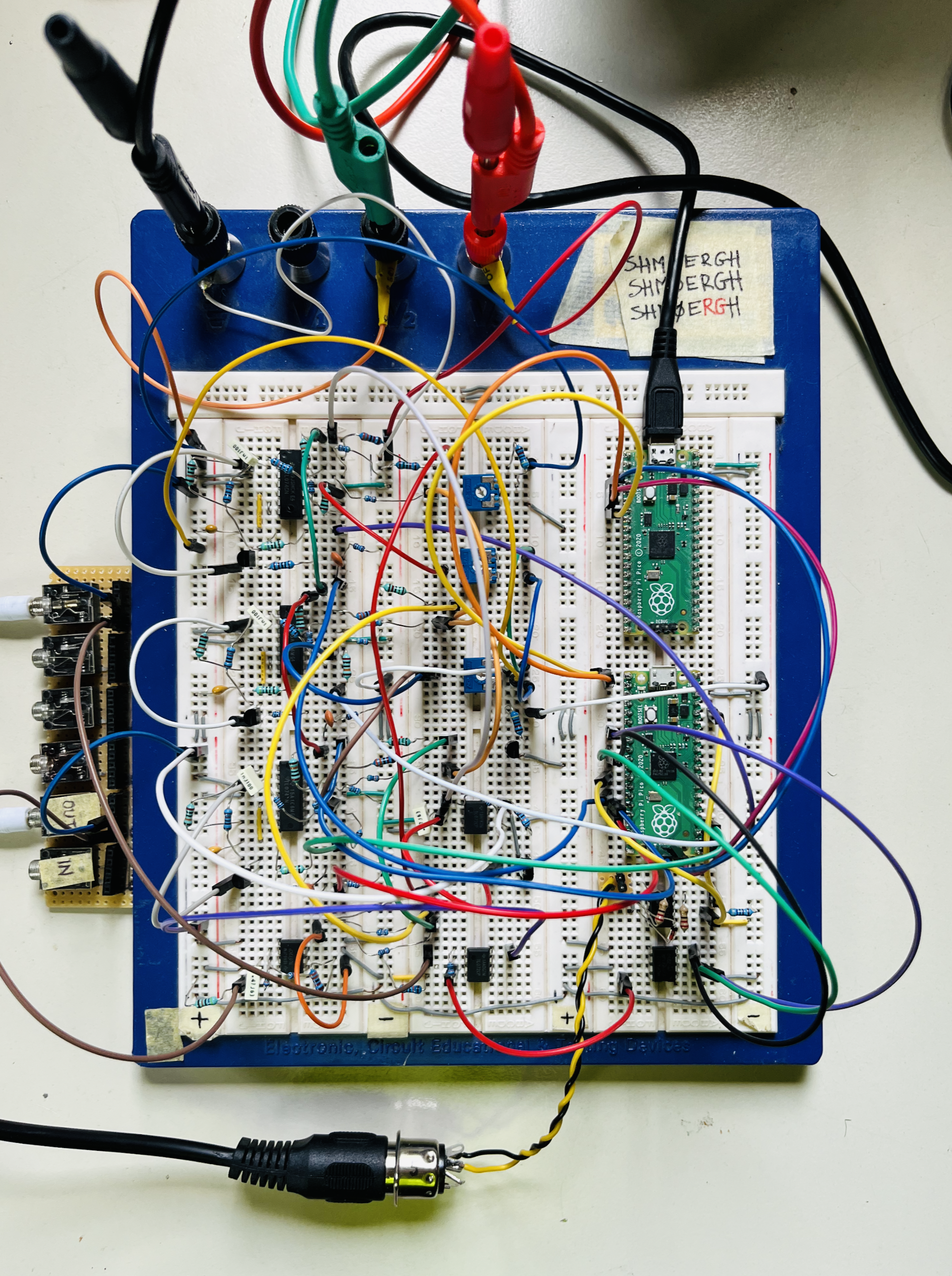
While there are lunatics like Ben Eater who build a full-on 8bit computer on a breadboard, a project at the size of the Hog is too much for me to prototype all at once on breadboard. Instead, I breadboard a single module, make sure it works and move on to the next one. Once all looks good I design the printed circuit board (PCB).
PCB design
There are many-many ways to approach PCB concept design for electronics projects. For the first two versions of the Hog I went with the safest option and created each module on a separate board — essentially coming up with a pre-wired Eurorack system in a box.
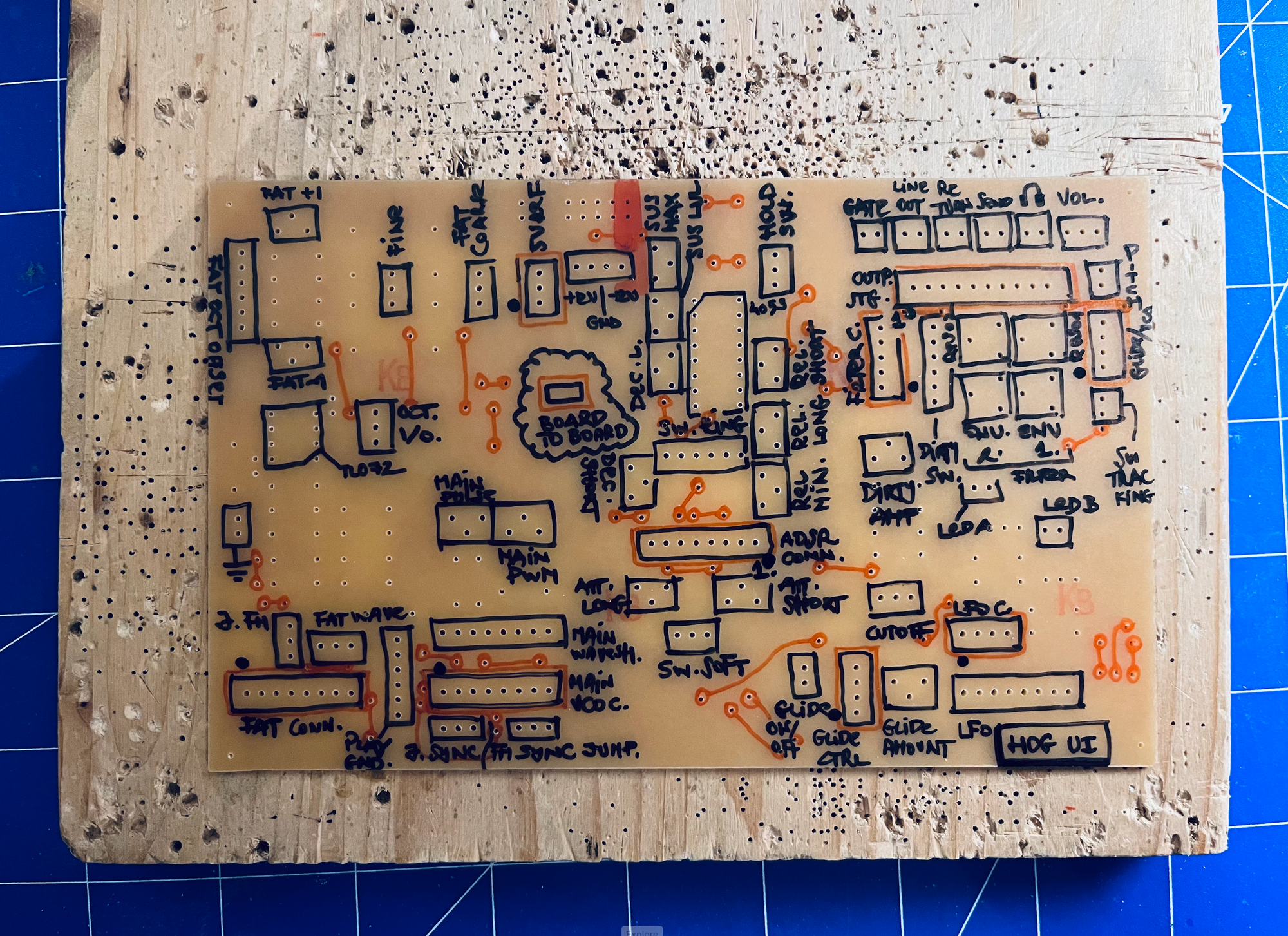
The first versions of these boards are completely home-made on empty, photo-sensitive PCBs, using chemicals and shit. When the etching is done, I drill holes on the board and solder the components on.
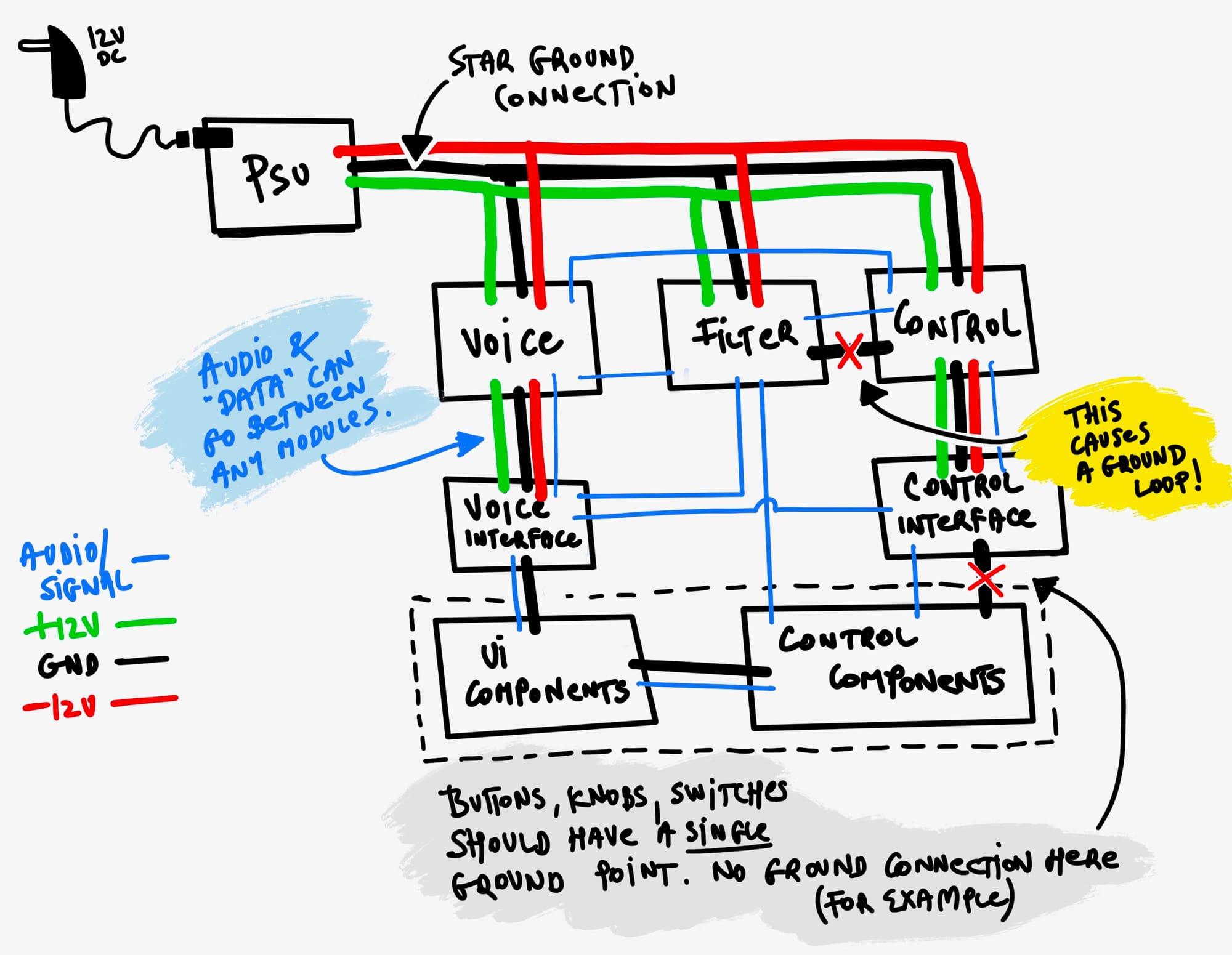
Boards connect to each other through standard connectors with cables. Creating these connections is probably the most time consuming part of the whole process. Also the end result is an incredible rat nest of cables which are very noise prone. Just look at the mess inside poor A1 😬

It took me about 3 months to design and build each board with the above process. Of course I also had to make sure that the PCBs fit in the box we were planning to use for the instrument.
Enclosure design
The first version of this synth was put in this metal IKEA flower pot. It not only looks great but also acts as a Faraday-cage which is essential for sensitive circuits like a diode-ladder filter.
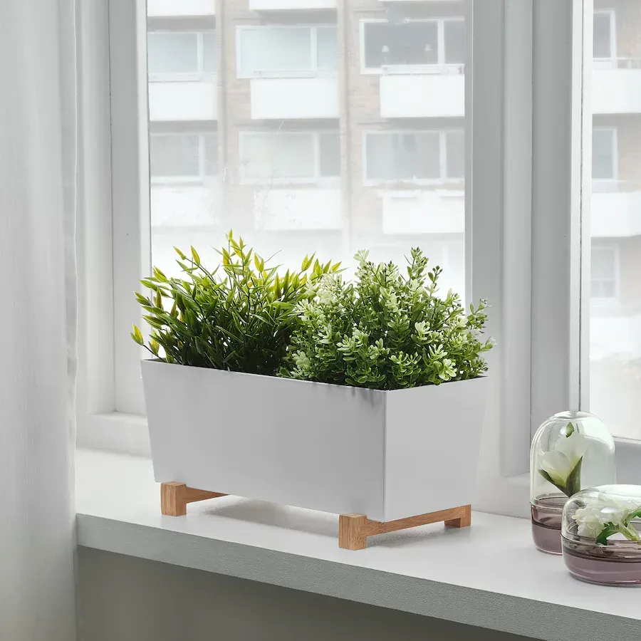
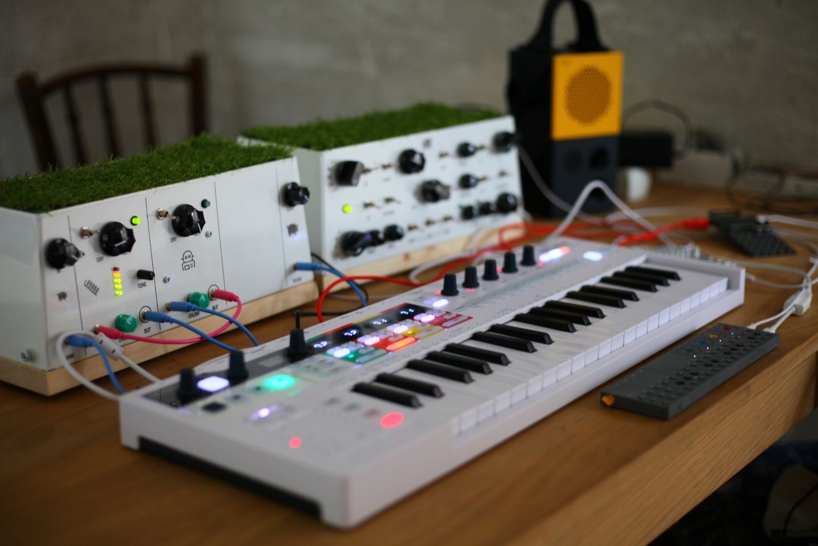
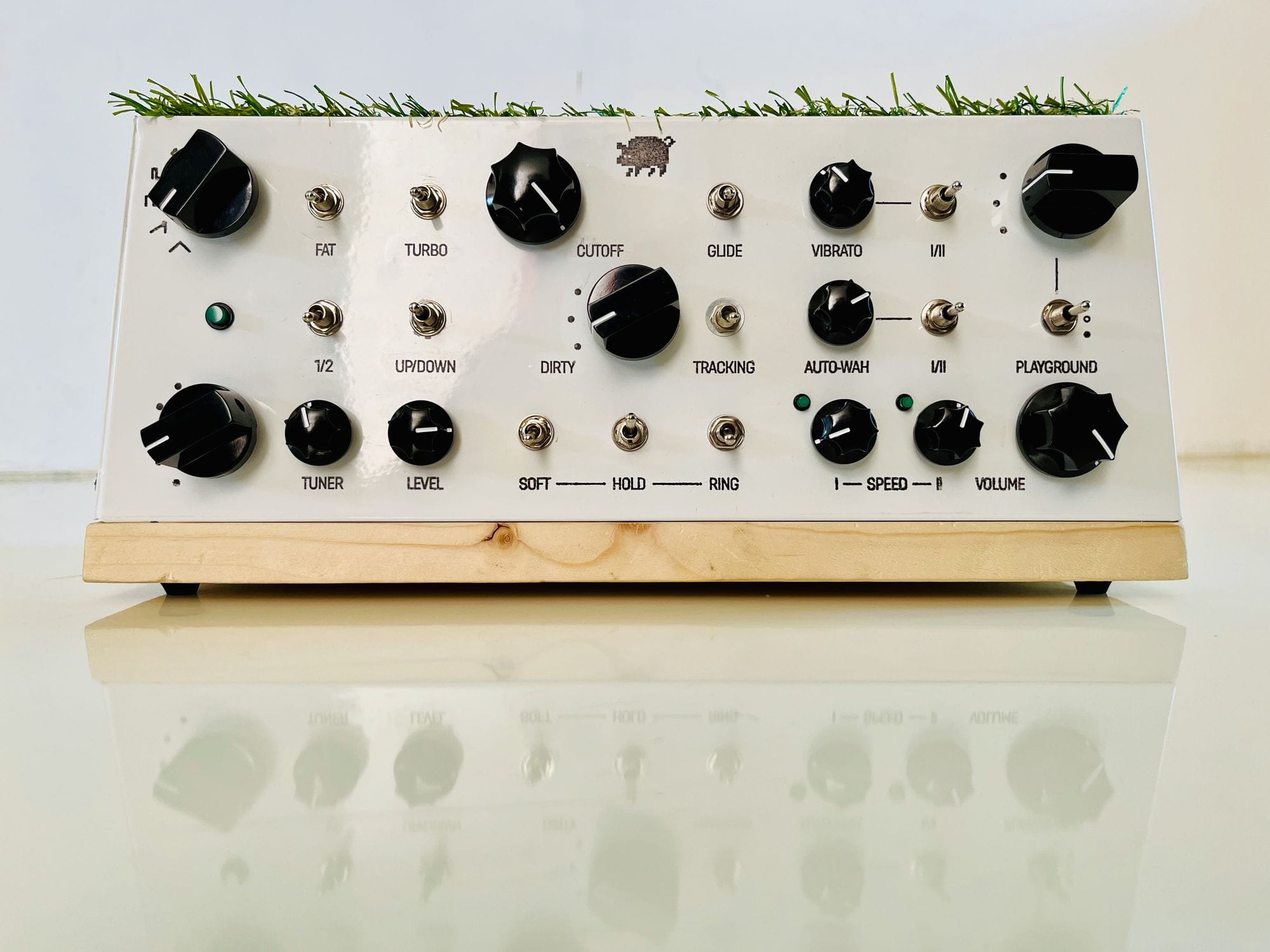
First photo: ikea.hu
There wasn't much to design on this box, the hardest part was to fasten the bottom wooden piece to the upside-down pot. Eventually the first version came out pretty good, here's Illés (AKA Dr. Tre) and me having fun with it.
Custom enclosures
Once the first prototype was done, we had an idea to put the same electronics in various boxes. After all, the core electronics is completely decoupled from the UI (knobs, buttons, switches) so we can do whatever we want until the PCBs fit in the box. Seemed fun enough to do it.
The process was pretty much the same except that instead of manually etching all PCB's at home I redesigned the boards and ordered them from JLCPCB. While this saved some assembly time, modules were still on separate PCBs and soldered manually. At the end it wasn't really significantly easier or faster so the only synth we ended up building was one in another IKEA box.
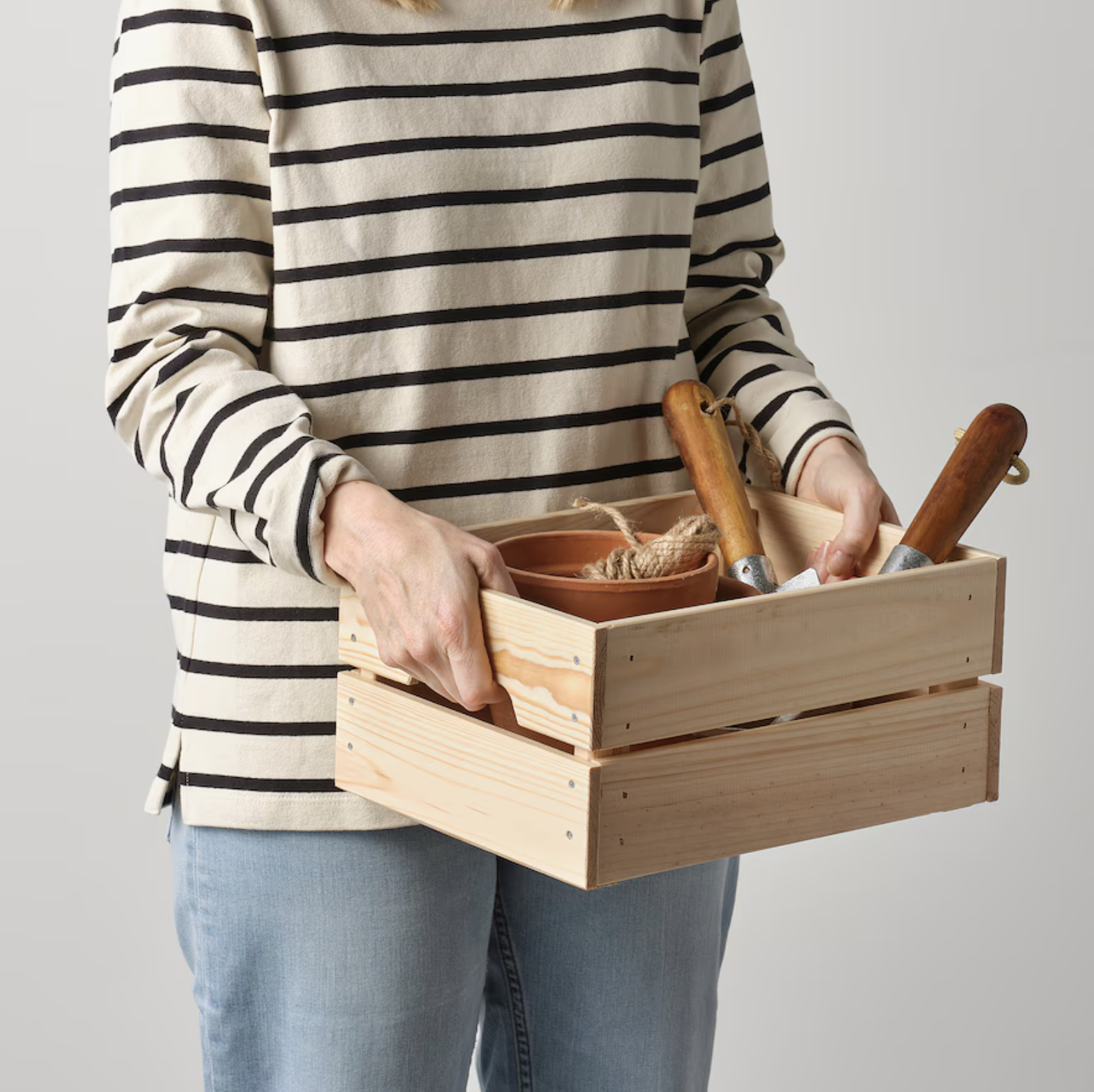
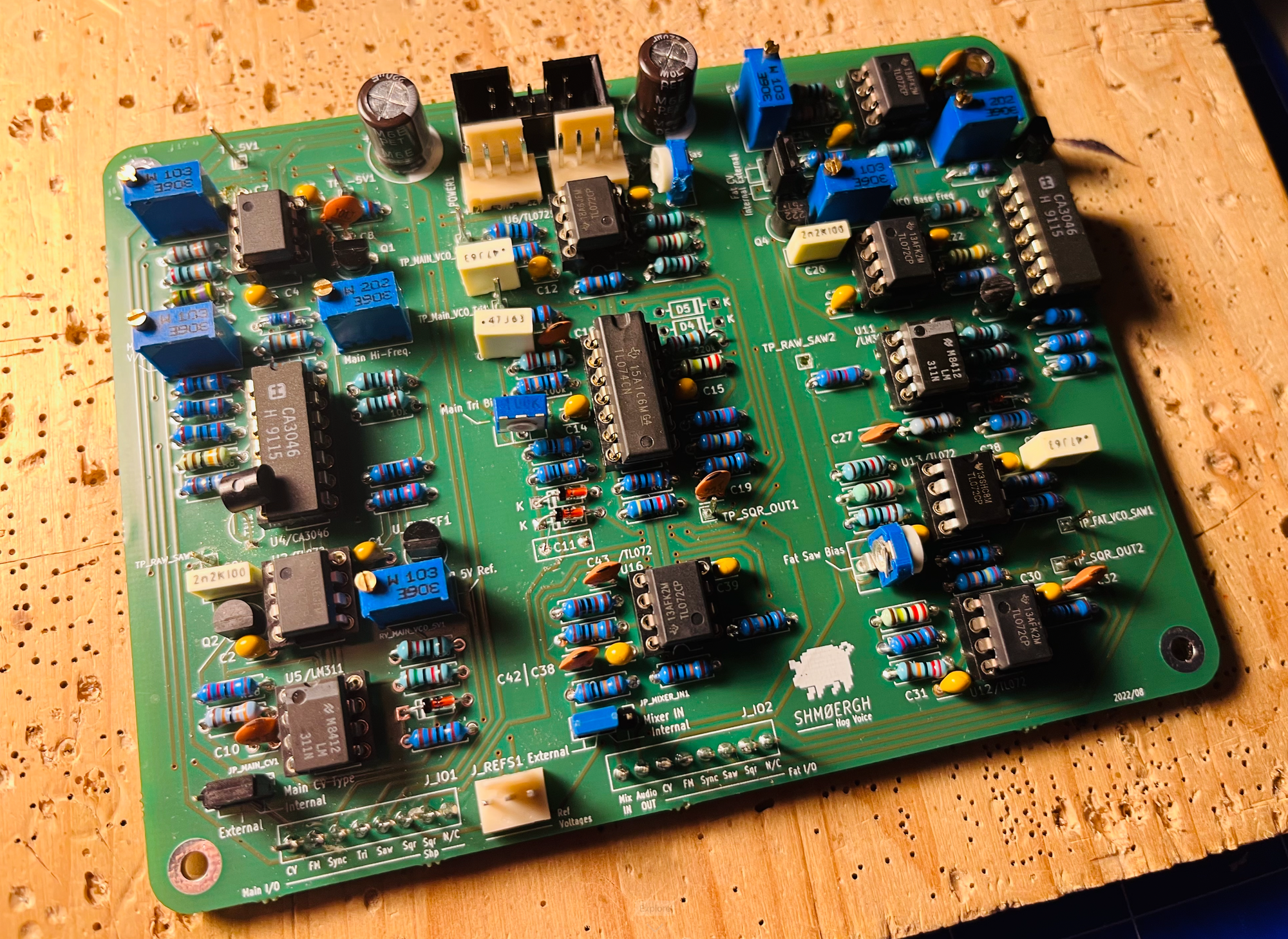
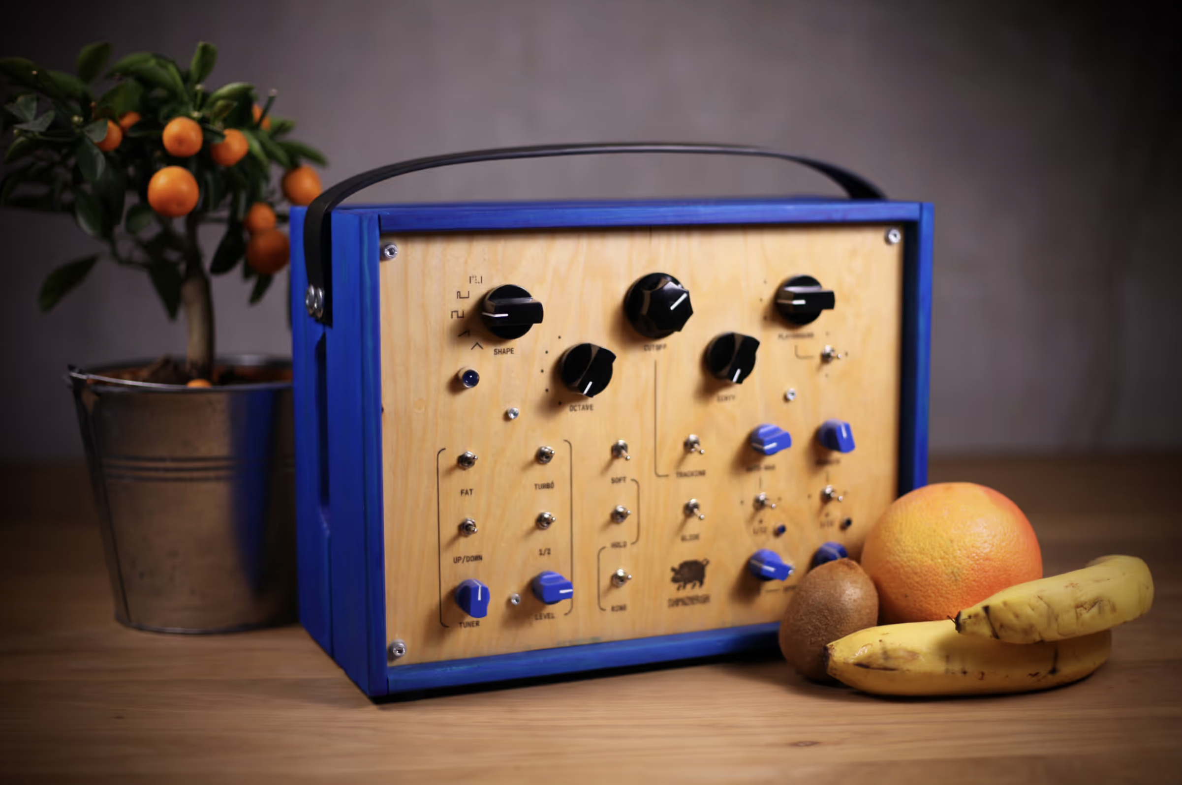
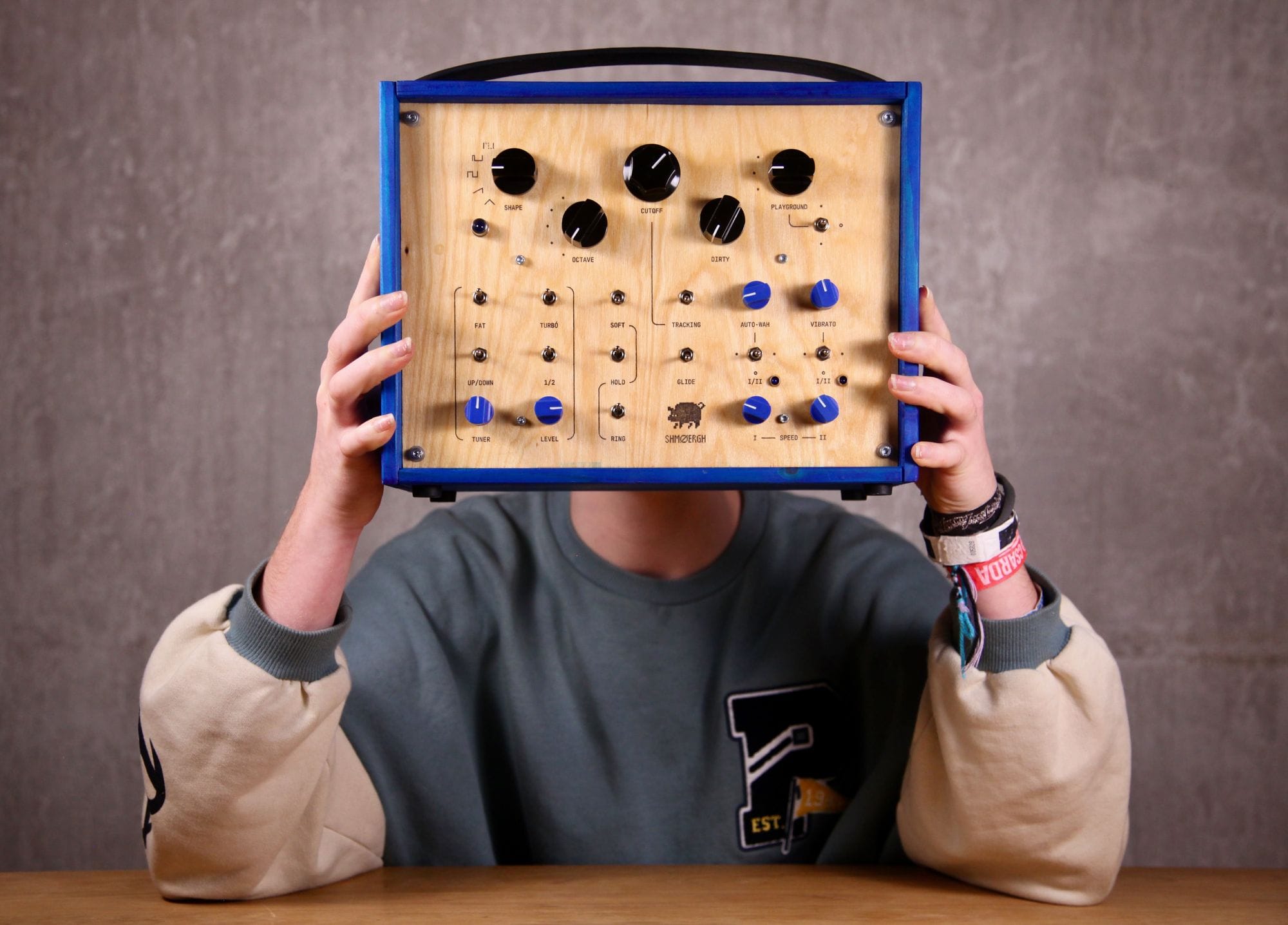
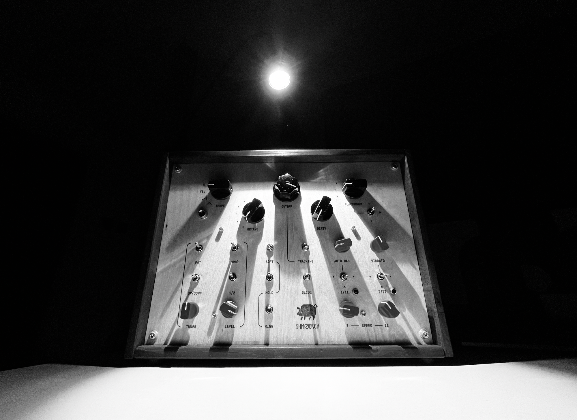
Second iteration of the Hog. (Photo on the top left: Ikea.hu)
Out of the shed
Our ultimate goal with the Hog is to get it in the hands of musicians who will actually use it. For that we knew we needed a circuit design that's significantly faster to build and a casing which is reproducible and sturdy. This meant much fewer PCBs and a custom enclosure design.
(Almost) single board design
There are two extremely time-consuming part of manually building electronics: soldering and creating connections between boards. So my next plan was to reduce these as much as possible by using surface mount components, third-party PCB assembly, and a new design with significantly less boards. However, we wanted to keep some flexibility for potential future use cases and reusability so I divided the circuit to four main boards:
- Power supply — probably the most critical and important part of the system. I wanted to keep this on a separate board in case components are not available in the future or I want to experiment with different powering solutions.
- Core board — a single board with all the modules except for the filter. These core modules are well tested and pretty much the same regardless of final synth. 90% of the components on this board are surface mount and assembled by JLCPCB.
- UI board — switches, knobs, LEDs, everything visible and tangible on the front panel. Separating the UI board from the core allows completely different concepts in the future: for example a fully adjustable synth for sound design.
- Filter — filters are responsible for about 80% of the final tone of a synth, many times it makes or breaks the sound of the instrument. Keeping it separate lets us explore with different filter architectures in the future.
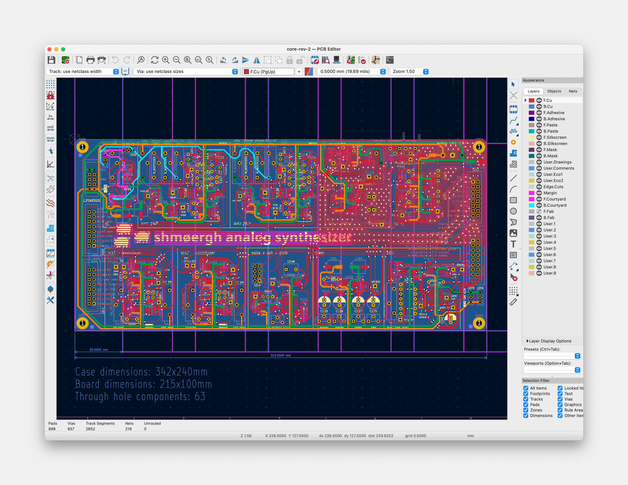
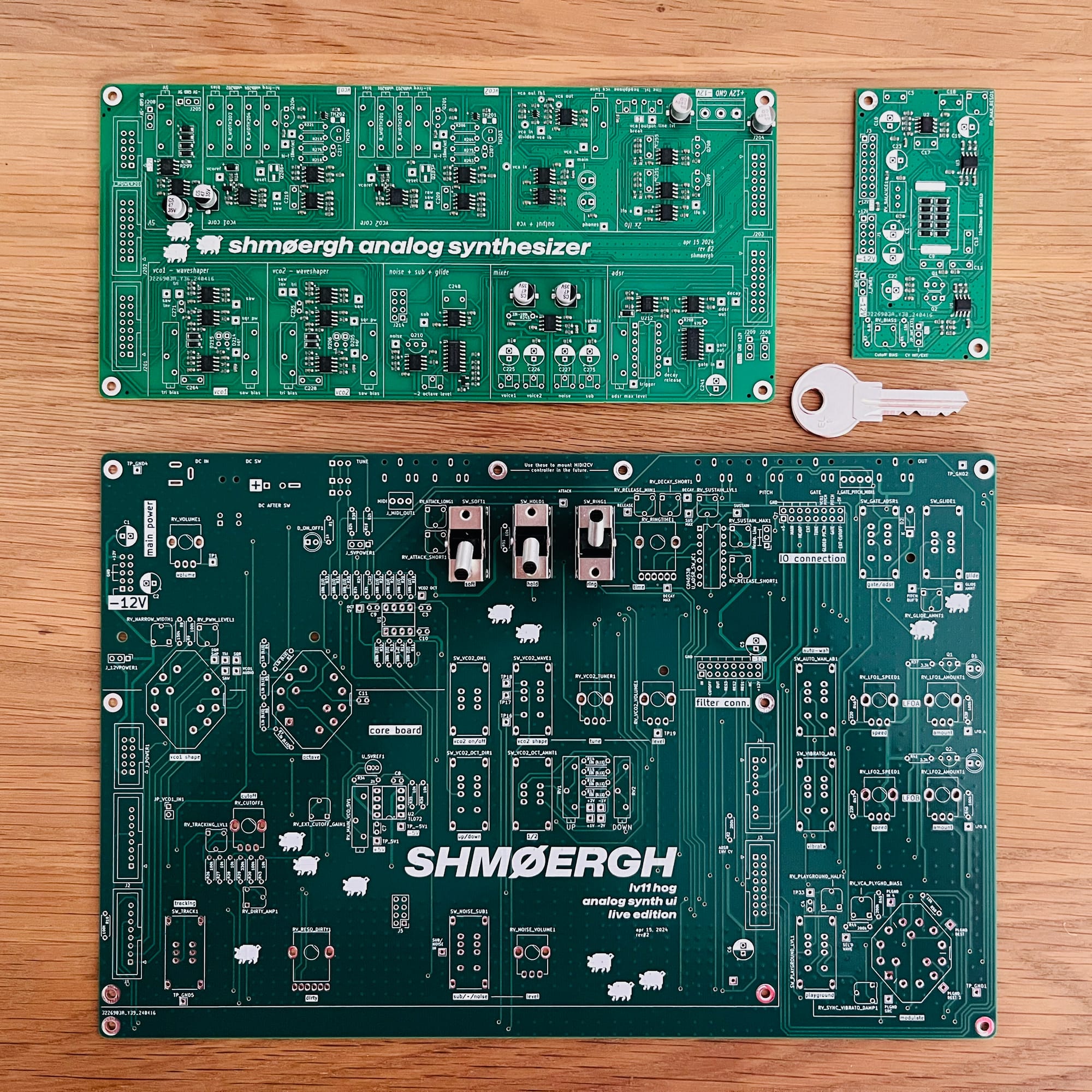
Stainless steel enclosure
Probably one of the most fun part of a synth design is the enclosure. Since we want to make each Hog unique I designed a system that allows enclosure variety and potential new instruments in the future with the same box dimensions.
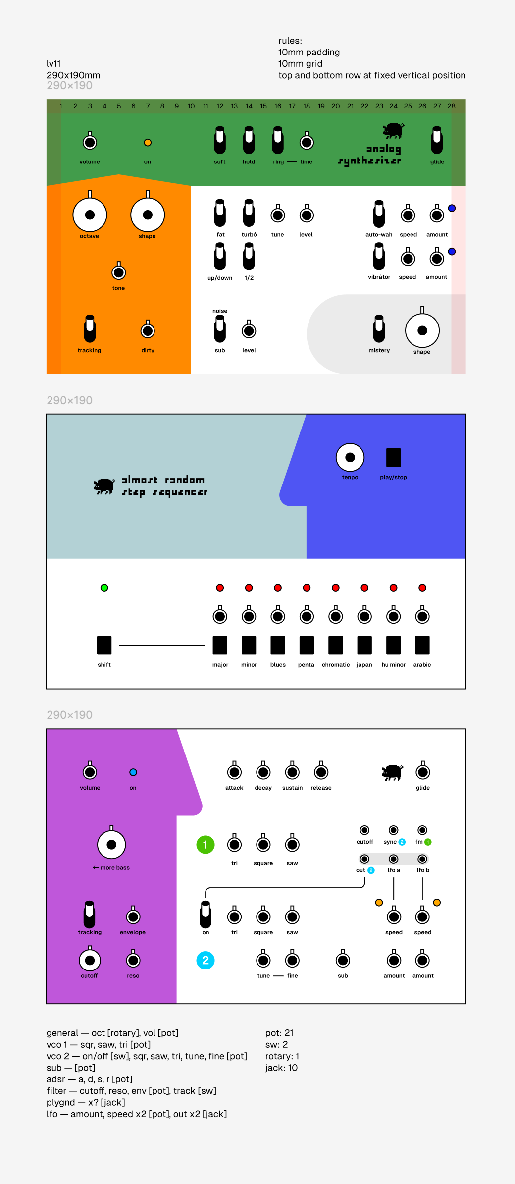
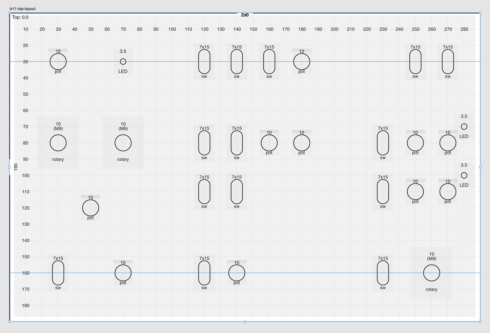
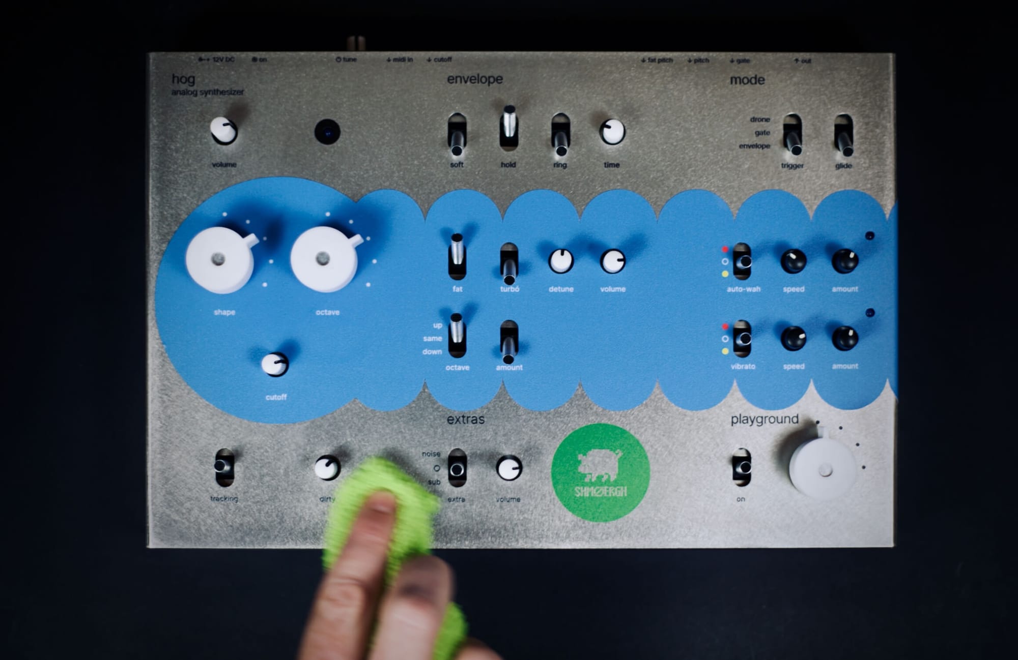
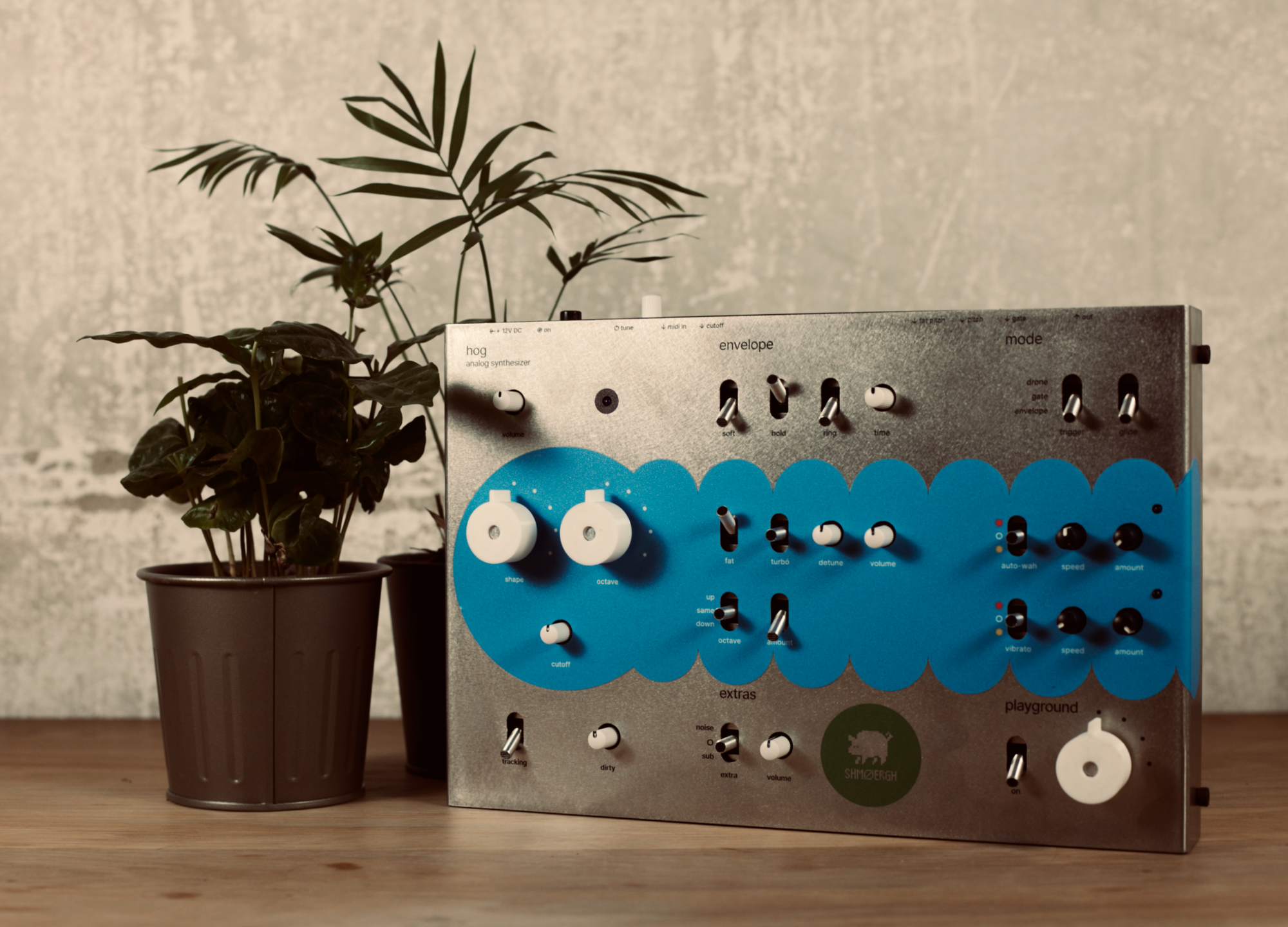
The final design is based on a 10x10[mm] grid and the final box is approximately the size of an A4 paper. The enclosure is built up from two complimenting U shaped bottom and top parts, the material is 1mm stainless steel. The sheet metal parts were designed and manufactured by Flame. He used FreeCad, a free tool which is kinda the cousin of KiCad for industrial design.
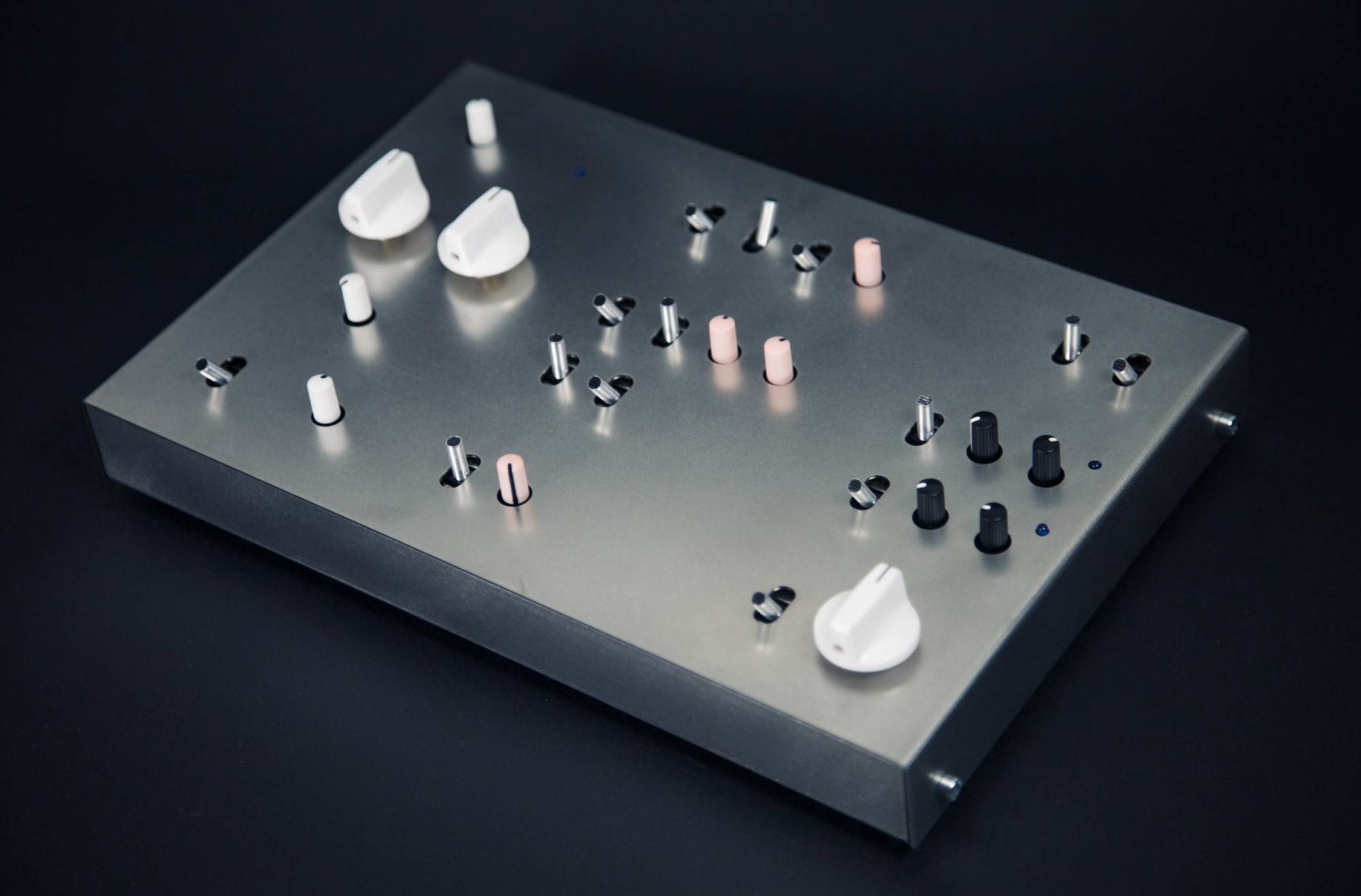
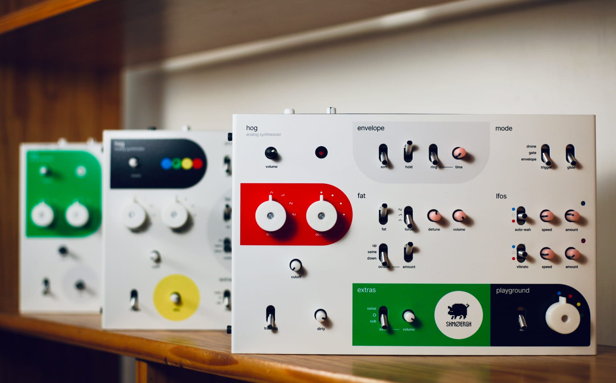
I designed the graphics for the enclosure. My idea was to have a unified feel but different design for each synth, so that each owner can have a unique instrument. For the first batch (5 synths) I wanted something approachable, timeless, fun and easy so I chose simple geometric shapes and very basic colors and fonts.
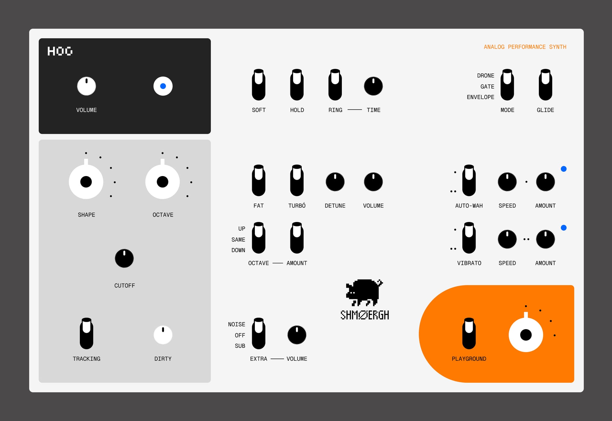
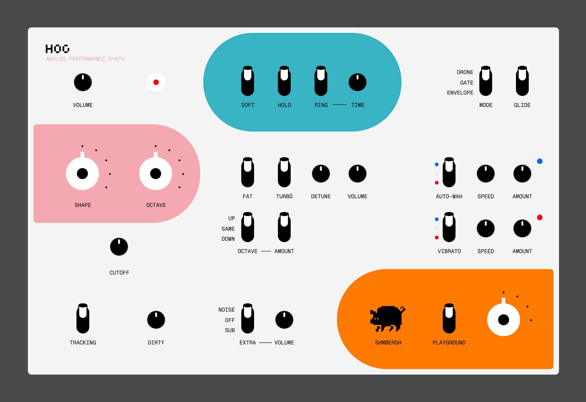
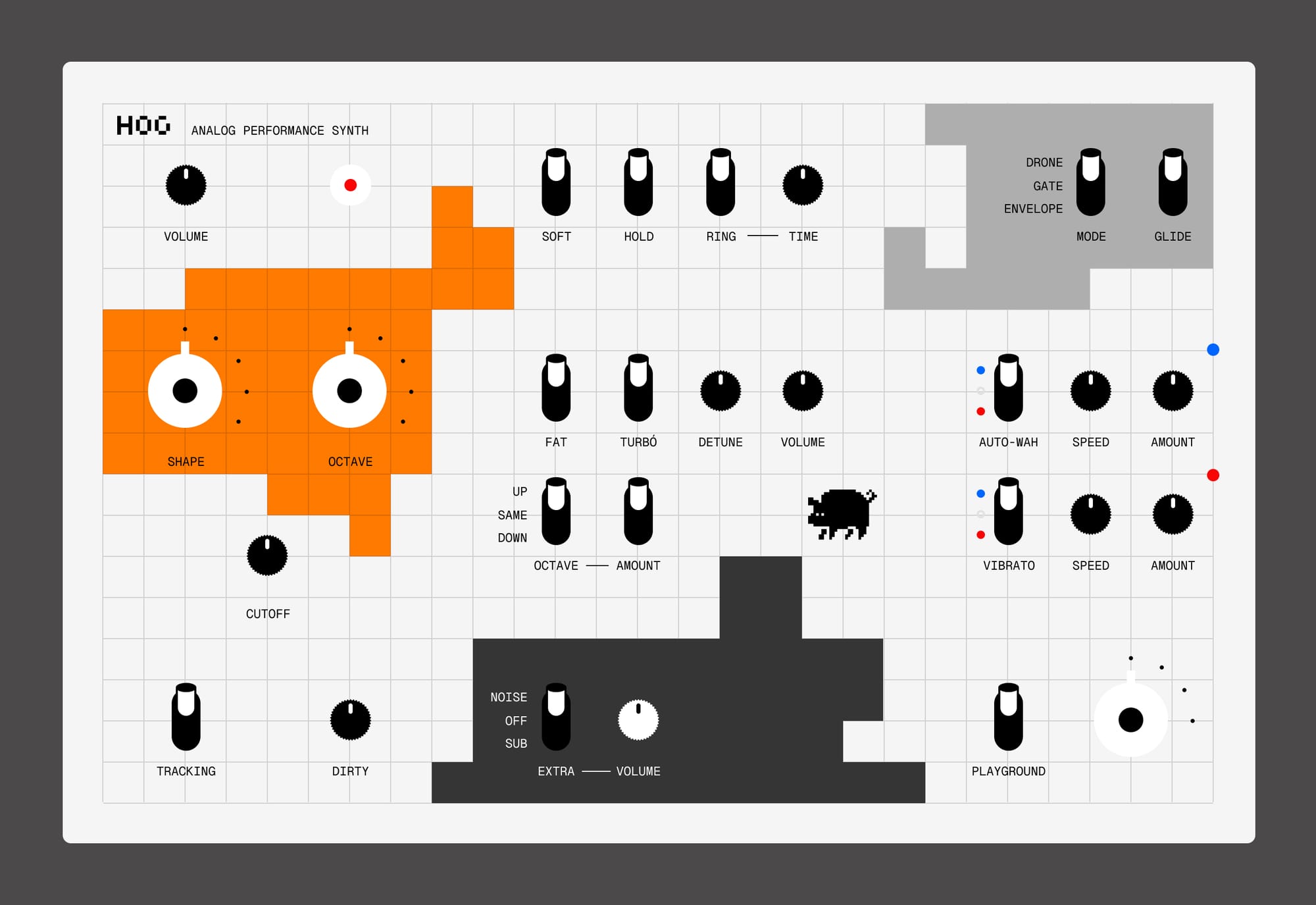
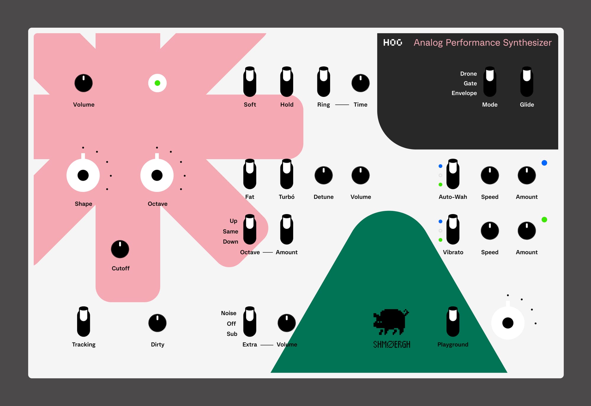
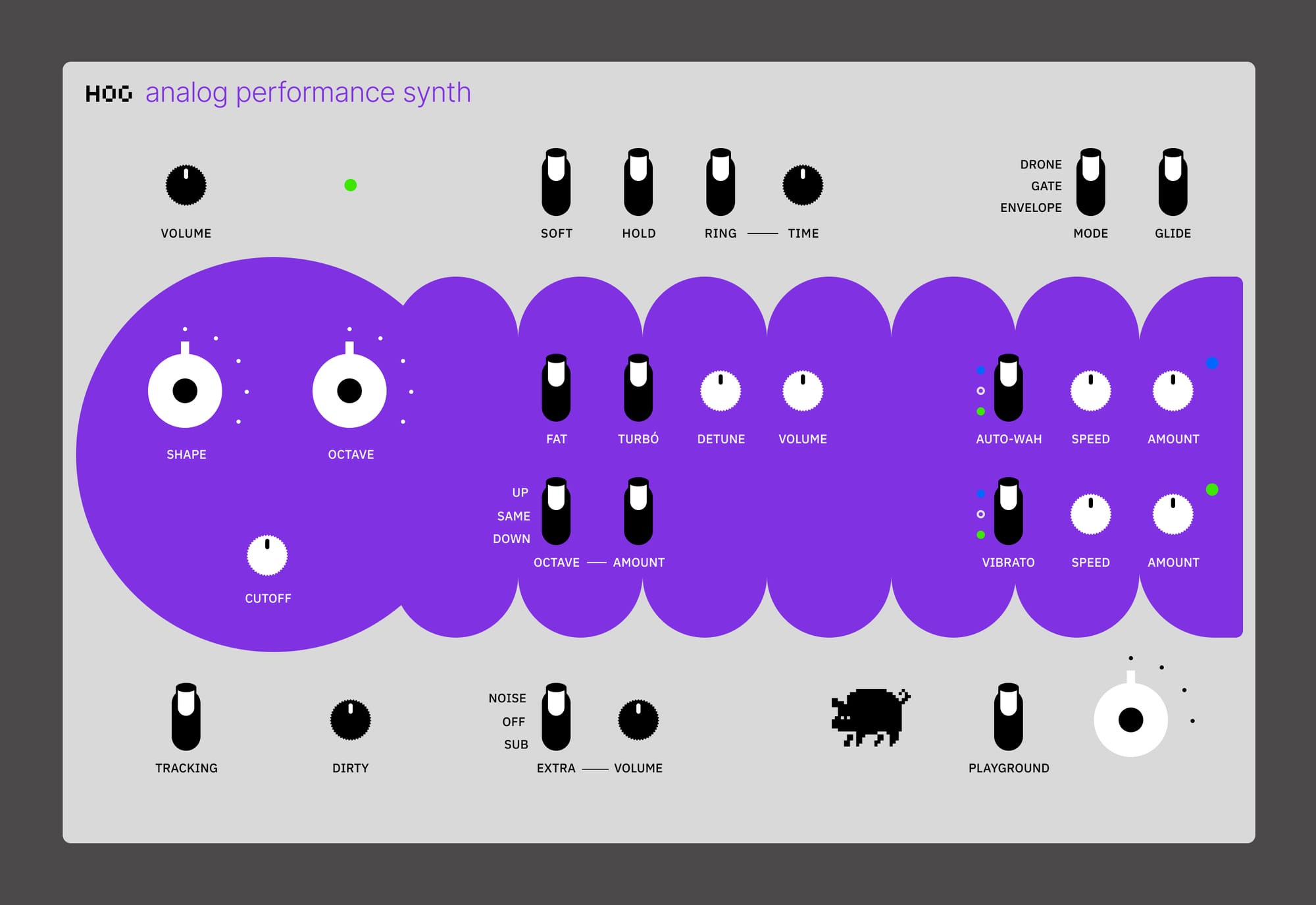

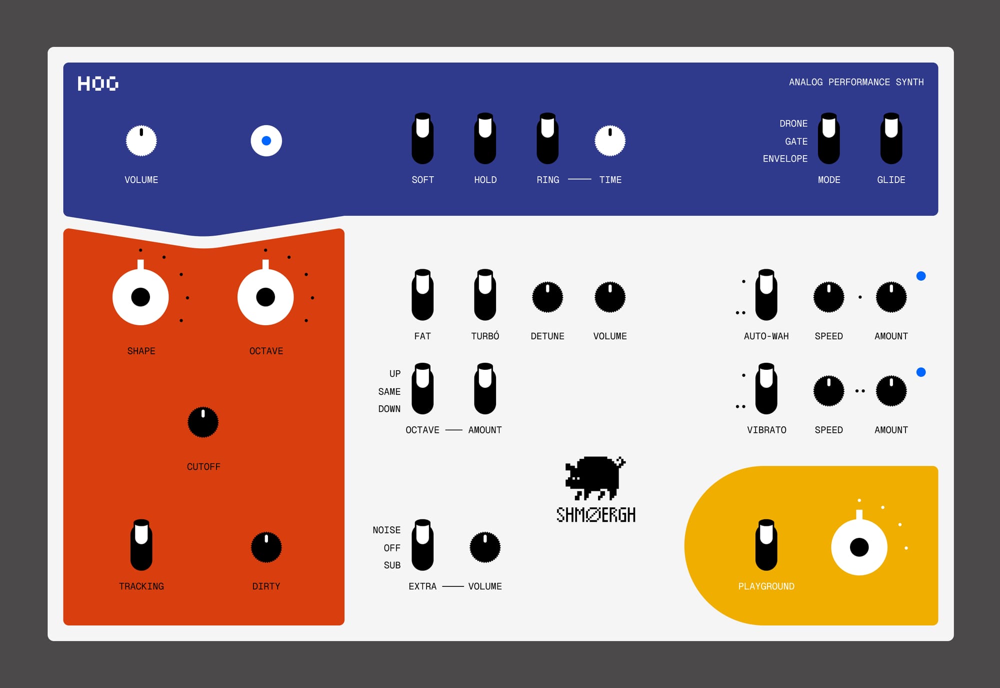
Hog graphics exploration
Here's the final five design that we settled for the first batch. We went with pure and basic colors and geometric shapes. The one with the worm we kept non-colored stainless steel and used a sticker for the worm so it can flow down on the side of the synth.
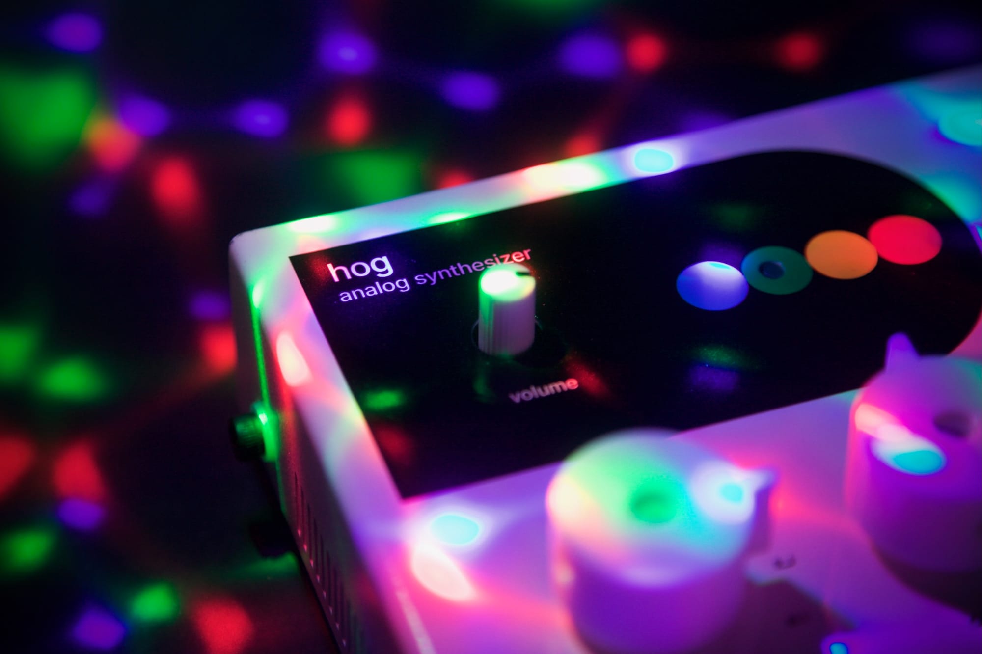
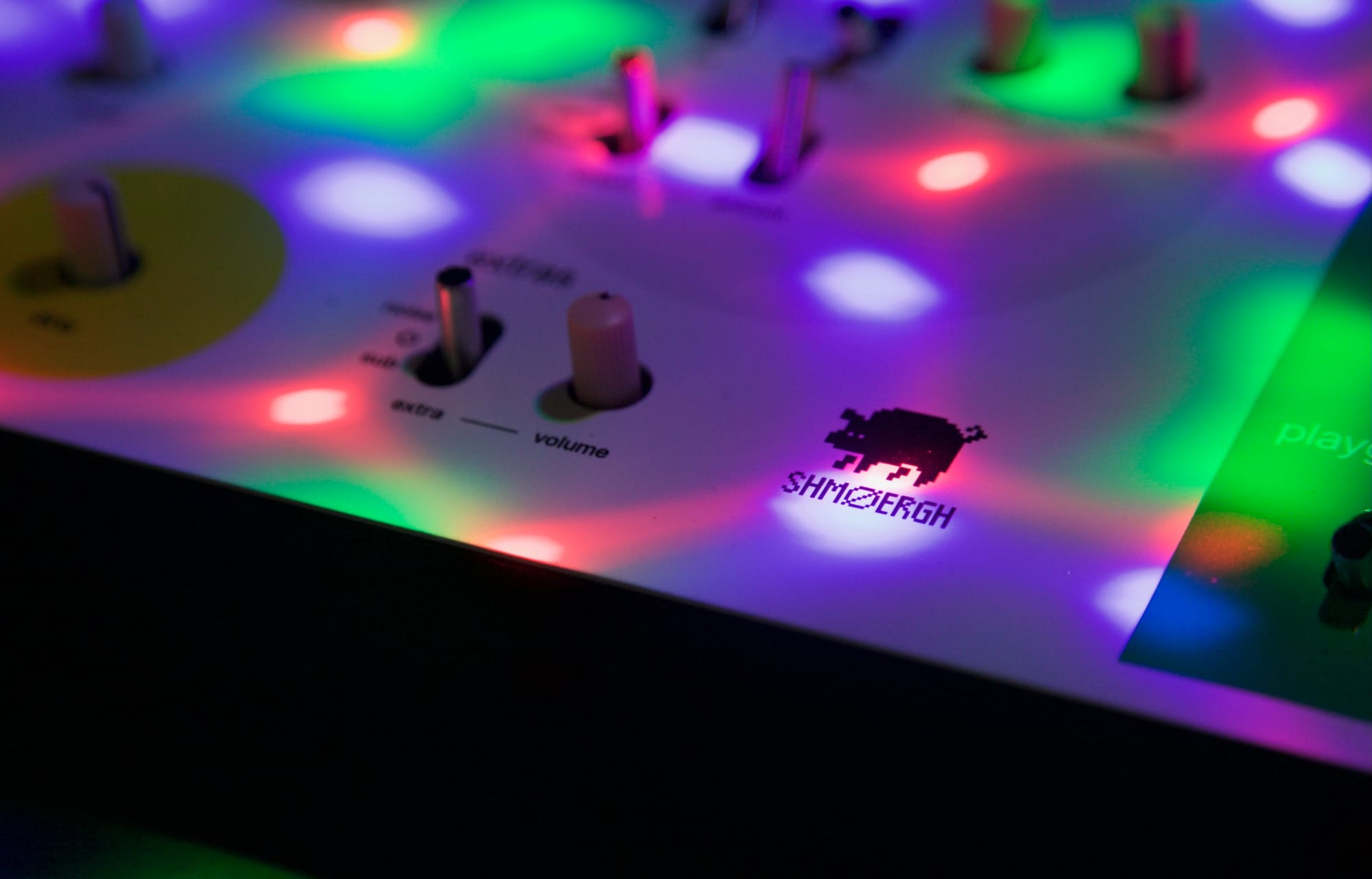
For the rest, the top and the bottom parts of the enclosure are powder coated in plain white and black colors and the graphics are printed using UV printing technology. Unfortunately we learnt late in the process that UV printing on powder coated surfaces are quite fragile, so some scratches are visible on the boxes. Therefore we coated the top with multiple layers of acrylic lacquer to avoid scratches as much as possible.
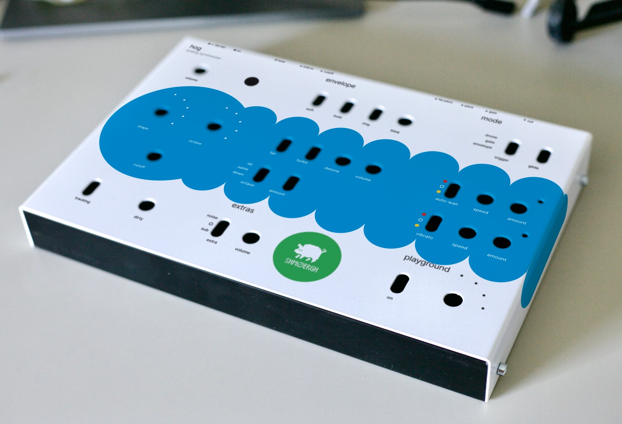
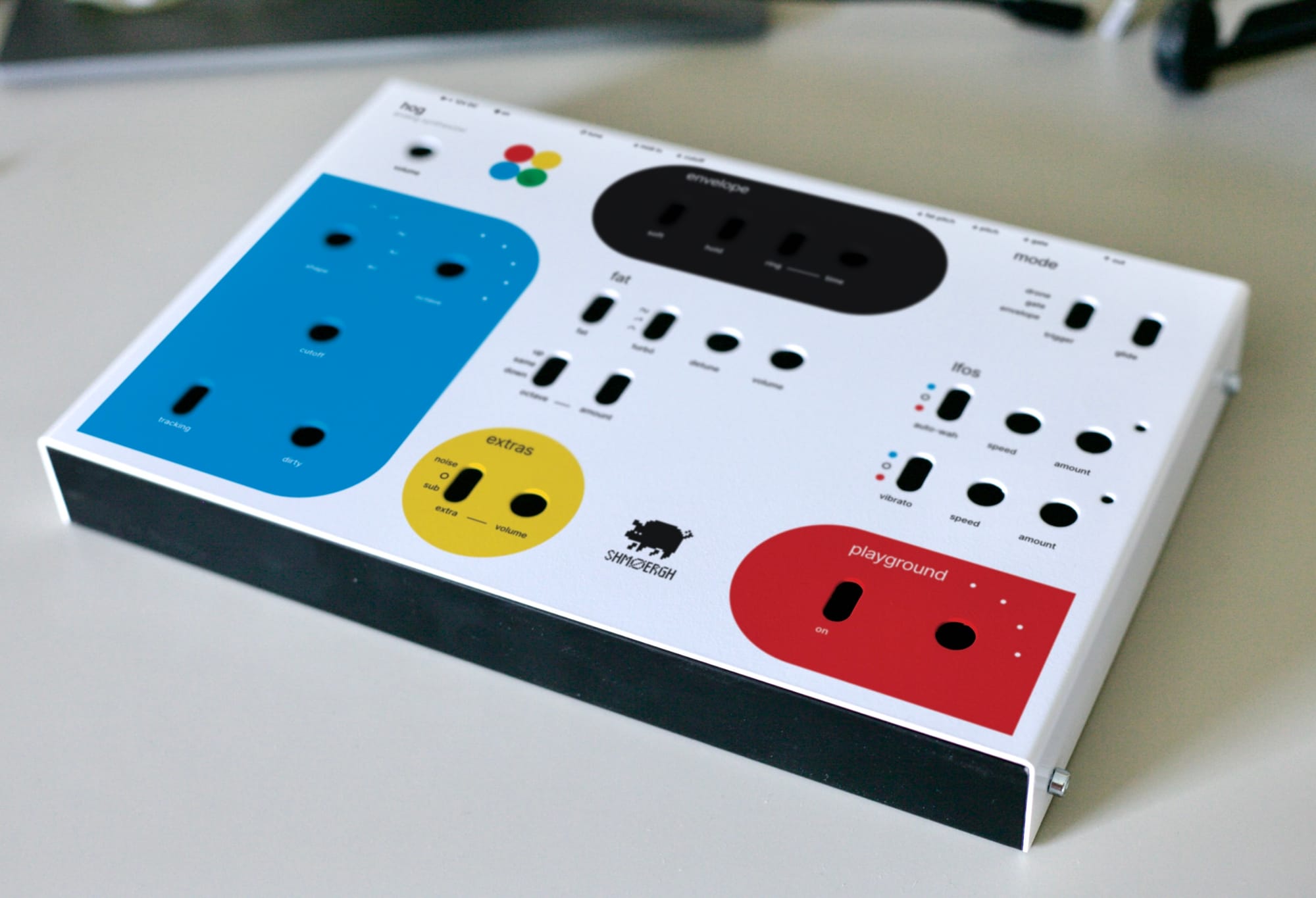
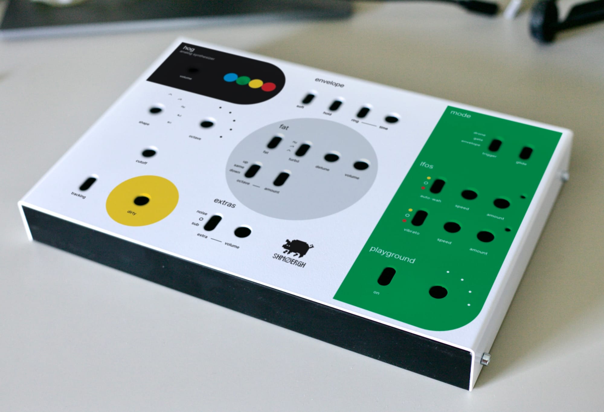
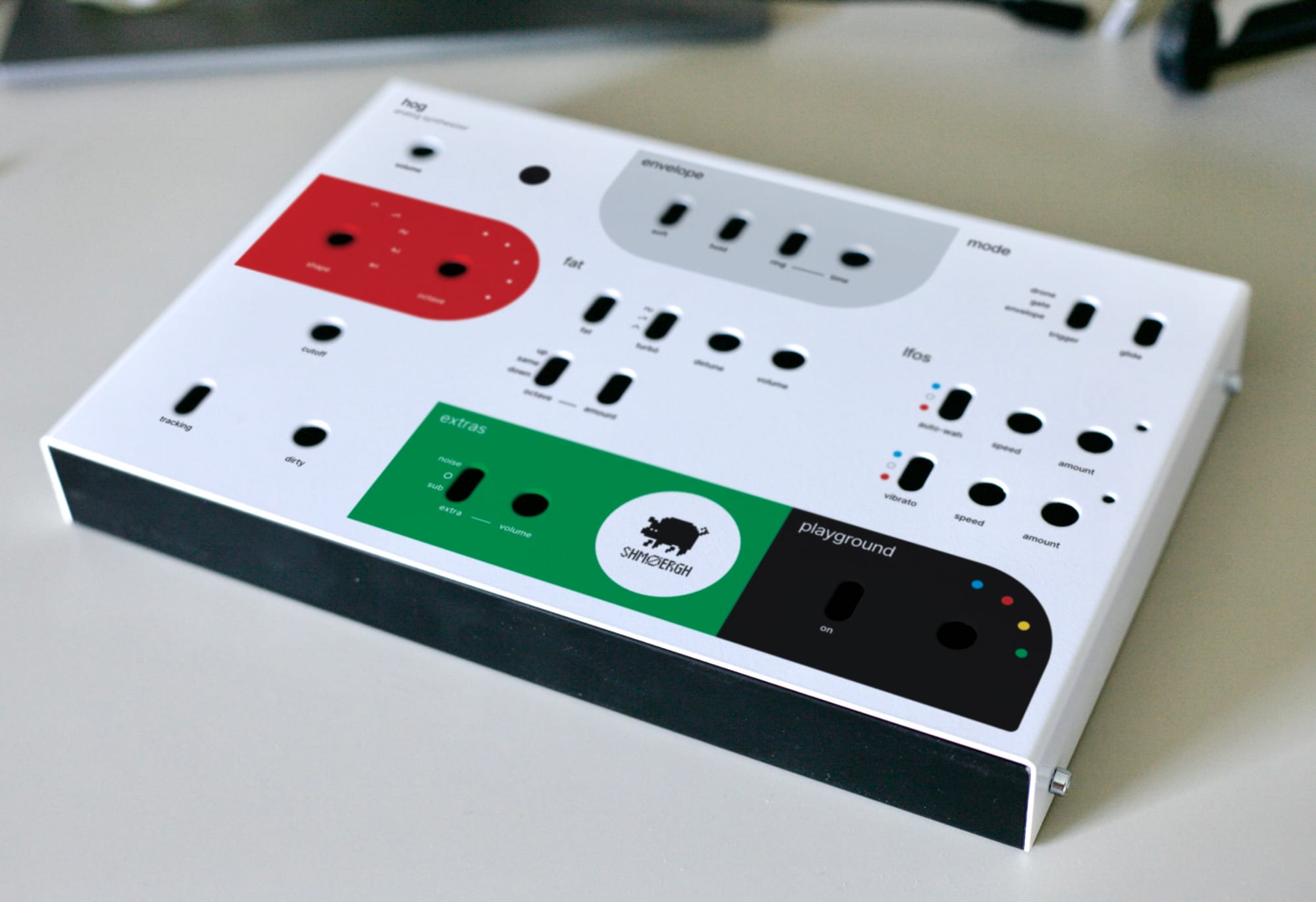
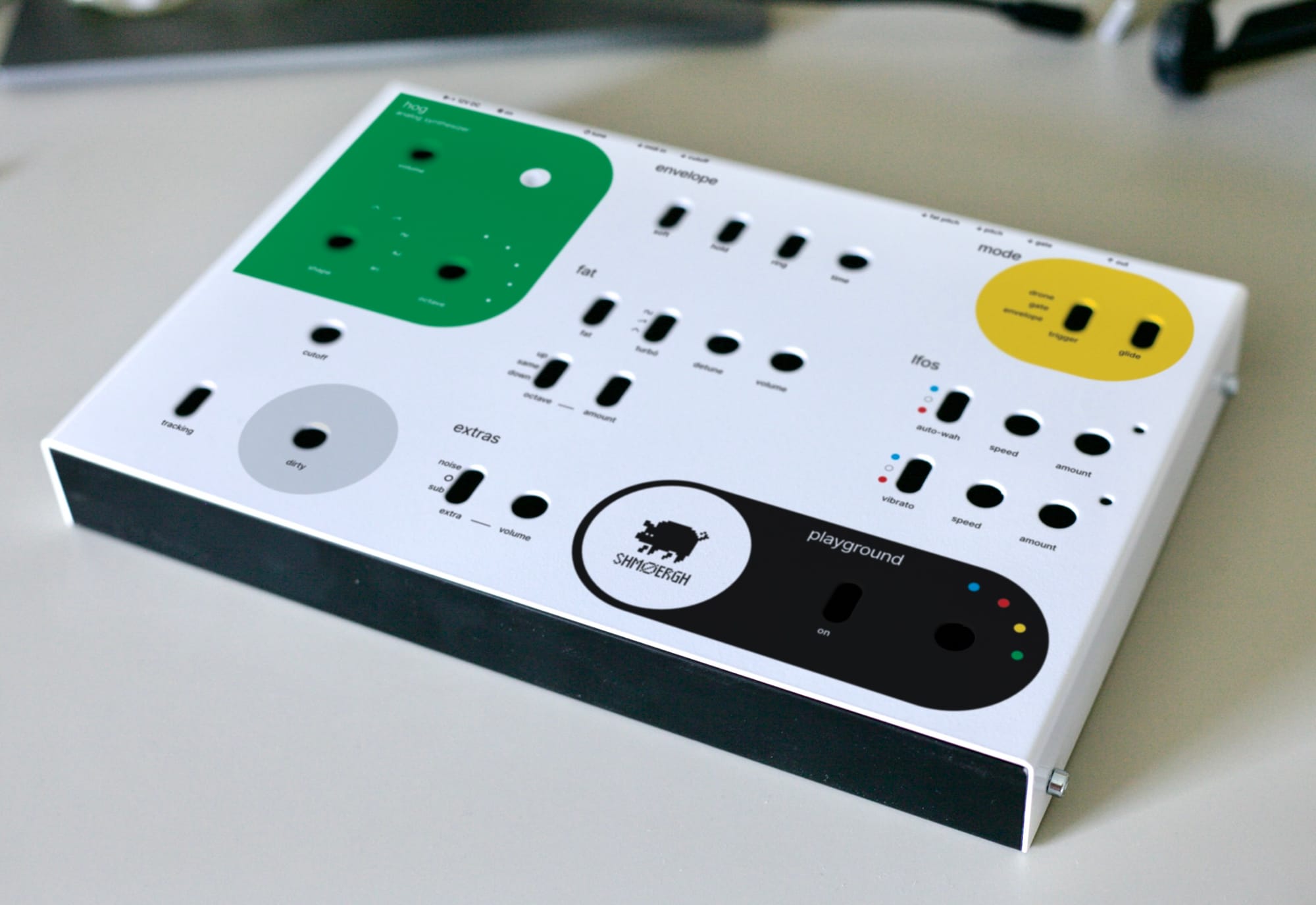
First batch final graphics (mockups)
The above pictures are mocked in Affinity Photo but honestly, the end result (below) is quite shockingly close to what we designed.
What's next?
As I wrote a couple times, we don't intend to mass-produce the Hog because mass-production is a completely different beast. It's a huge financial investment which requires full focus. Designing the product is just a very-very small thin slice of the whole and most of the time and money goes on everything else: marketing, sales, support, complying regulations just to mention a few.
Also, the concept of the Hog is to provide a unique instrument to each owner. If we wanted to mass-produce the Hog we'd need to drop this concept and unify everything. This might happen in the future but right now, there's a very small chance to it.
Okay, so what's next?
Yeah, so instead of mass-production we still want to keep our craftsman-hats on and build just a few Hogs for some good friends, with the hope that they will find joy in a simple analog synthesizer. If you're interested in getting one of them, let me know (at peter zimon gmail).
Resources
The complete design of the Hog is available for anyone at the Shmøergh Hog build guide.